BOLT, Two Pass IR Interpreter
Written: , Published: , Author: Kimberlee Model, Tags: SIEVE IR, WizToolKit, v1.0.1, outdated, but still super cools,
In this installation about the SIEVE IR, we’re going to talk about speeding up a proof system without changing the underlying zero-knowledge mathemagic. When we time a ZK backend using the IR we inadvertently time two distinct components — the backend itself and the time it takes to ingest a circuit. The first component, the backend, is fairly well understood and many groups are working on optimizing this — faster math and less communication. The second component is the topic of today’s post; it’s the time spent reading a gate and loading its operands before it can be processed in ZK.
|
Note
|
If you’re looking for how to use BOLT, have a look at WizToolKit’s documentation for BOLT. This post is about how BOLT works. |
We first looked into this problem after noticing that interpreting loops and functions was significantly slower in the IR than the IO and parsing time for an equivalent IR-Simple circuit — contrary to our expectation. While some of the weaknesses outlined in our IR Retrospective certainly exacerbate the issue, we also stumble into the age old conflict of interpreters vs. compilers (Python vs. C, etc.). While we have developed an extremely performant IR compiler, this post focuses on interpreters for the IR and takes half a step towards Just-In-Time (JIT) compilation.
The largest source of overhead which we encountered is searching for wires in lookup tables. With loops and functions the lookup table must be built, destroyed and rebuilt on each iteration or invocation, causing significant slow downs. We solve this problem by building an in memory data-structure where a single lookup table is built once and reused on many occurrences, and where each lookup operation is cached as a pointer into the table. At the time of writing, we have already developed a partial prototype of this system. This post will start out with results from the prototype in a non-ZK setting, then it will narrate development of the full system, and overview some results using the EMP-ZK backend.
If you’re unfamiliar with the SIEVE IR, you’ll want to read our IR Introduction and Retrospective before reading this. You should also be prepared for some proof by induction and UML. We also clarify the following terms. Overhead, in this context, is any time spent by a ZK proof system which isn’t directly related to the proof, so parsing and compiling or interpreting the circuit. The parser is the first stage of processing the IR in which a sequence of characters matching the IR’s grammar is converted into a parse tree (or synonymously, syntax tree). Both an IR compiler and interpreter will parse the IR, but the compiler will analyze the parse tree and produce an executable program which then performs the proof, while the interpreter will analyze the parse tree and perform a proof without an intermediate executable. We further classify single-pass interpreters which immediately walk the parse tree and perform one step of the proof at each node, and multi-pass (or two, three, etc. -pass) interpreters which walk the tree multiple times, first doing analysis and building state data, then finally performing the proof.
Prototype and Early Results
Our prototype succeeded in accelerating many samples of the IR, but it also entirely failed to interpret @switch statements and certain classes of @for loops.
Further we only developed it in a non-ZK setting.
That seems like a big failure for a supposedly ZK piece of equipment, but it gives us a lower bound the entire proof system’s runtime, e.g. how long would the proof take if ZK were entirely free.
After parsing, the prototype works in two phases. First, the build phase analyzes the parse tree and rebuilds it with embedded lookup tables and cached pointers into those tables. The build phase is able to embed most public semantics (such as "repeat this loop 5 times") into the tree. Then the evaluate phase traverses the optimized parse tree and invokes a callback to handle each gate’s private semantics (such as "prove that `a * b == c`"). In the prototype we only implemented gate callbacks for the non-ZK setting, hence this limitation.
We were able to compare our BOLT prototype with FIREALARM (our non-ZK IR interpreter for debugging and development) as a single-pass baseline. We used our matrix-multiply family of circuits as test inputs to show scalability of this solution.
The figure compares runtimes for each phase of the IR processing solution, further broken down by the IR’s mode (simple or using loops). It also shows target metrics for the SIEVE Program’s phases (arbitrary annual boundaries on our research). During Phase II our target metric is 1 µs/gate, which I’ve converted to wall-clock time for the appropriate gate count (red with dots). During Phase III our target metric is 0.1 µs/gate, again converted to wall-clock time (black with triangles). Note that wall-clock time for a particular solution would be each of its phases summed together (e.g. parse time + firealarm time or parse time + build time + evaluate time).
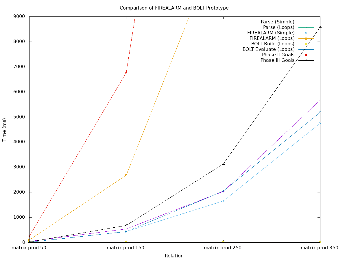
Before prototyping BOLT, the surprising result was that processing loops (orange with squares) was far slower than parsing (purple with vertical bars) and processing IR-Simple (aqua with stars). End-to-end, the IR-Simple solution takes 0.121 µs/gate (purple with bars plus aqua with stars), which is just a bit shy of the Phase III target and leaves no time for actually performing the proof. This discrepancy is what motivated us to develop BOLT.
The prototype improves upon this in a few respects. First, parsing additional iterations of a loop does not add to the parsing time. In fact, for this test case (and likely many others), parsing loops is a small constant runtime (green with cross, partially covered along the bottom). As it turns out, the build phase is also a nearly-zero constant (yellow with squares, along the bottom). This leaves the evaluate phase (blue with circles), which is on par with parsing or processing IR-Simple. Overall, the BOLT prototype managed 0.061 µs/gate, which leaves a tight margin for performing the proof, but also has room for improvement.
Approach
Before getting into the design of BOLT, lets go over a quick example to animate the problem and how we solve it. In the first animation, a vector dot product function of length 4 is shown. Each frame traces a step of processing the sub-circuit in a single pass. Many more frames show table lookups or insertions than show gate operations.
Our second animation shows the approach of BOLT. Rather than processing the parse tree directly, it is replaced with an alternate representation with pointers directly into a pre-built table. On each gate, pointer reads and writes save time when compared to looking up or inserting to the table.
Design
Before getting to the design, there are three numeric type abstractions.
The wtk::index_t (defined in wtk/index.h) holds a wire-index, the $ prefixed numbers indexing all wires in the IR.
The wtk::index_t is a simple typedef of uint64_t, thus capturing the mod-264 behavior described for loop iterator-expressions and wire-numbers.
After that, BOLT is template-parameterized by the Wire_T and the Number_T.
The Wire_T is to encapsulate all values which the ZK Backend must carry between gates.
BOLT does not require it be a numeric type, although it is sometimes easy to think of it as such.
The Number_T holds field-literal values coming from the parser, before they’re mixed into Wire_Ts.
BOLT has a pretty simple design at a high level.
BOLT connects directives directly to wires by rebuilding the IR syntax-tree and replacing the wtk::index_t indices with Wire_T* pointers.
The original syntax-tree is fairly straight-forward, mirroring the grammar of the IR.
The BOLT structure is a bit more complicated and with wires being cross-referenced from "directive trees" to their storage space.
Directives are a simple tree-like structure, the Bolt struct (for lack of a better name) being the entry point.
For most directives, an "in-order" tree traversal should produce a correct evaluation.
When loops or function-gates are encountered, repetition of a particular sub-tree produces the correct evaluation (this will be elaborated in later subsections).
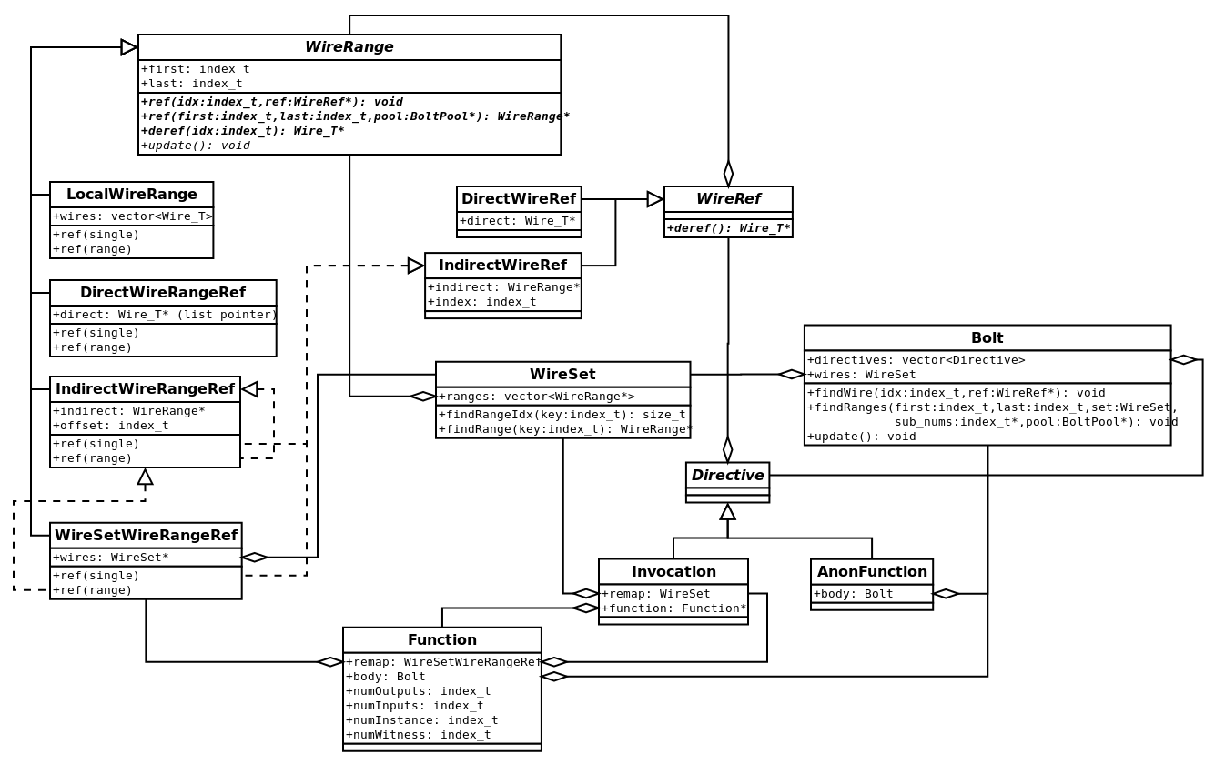
Wires are stored and looked up by the WireSet and WireRange families and connected to directives by the WireRef union-type.
The WireRef has two "addressing modes": direct, with a single pointer to a wire, and indirect with a pointer to and index in a WireRange.
BOLT does its best to use direct addressing as much as possible, however, indirect referencing is necessary when referencing for-loop iterator-expressions, or when reusing a function-gate at multiple call sites.
|
Important
|
Two class-families are implemented as unions while shown as inheritance in UML (which conveniently pretends that unions do not exist).
|
|
Note
|
BOLT (and WizToolKit in general) makes heavy use of a pool allocation pattern in which a "factory" or "builder" object produces some mess of structures, which take on the lifetime of the "factory". |
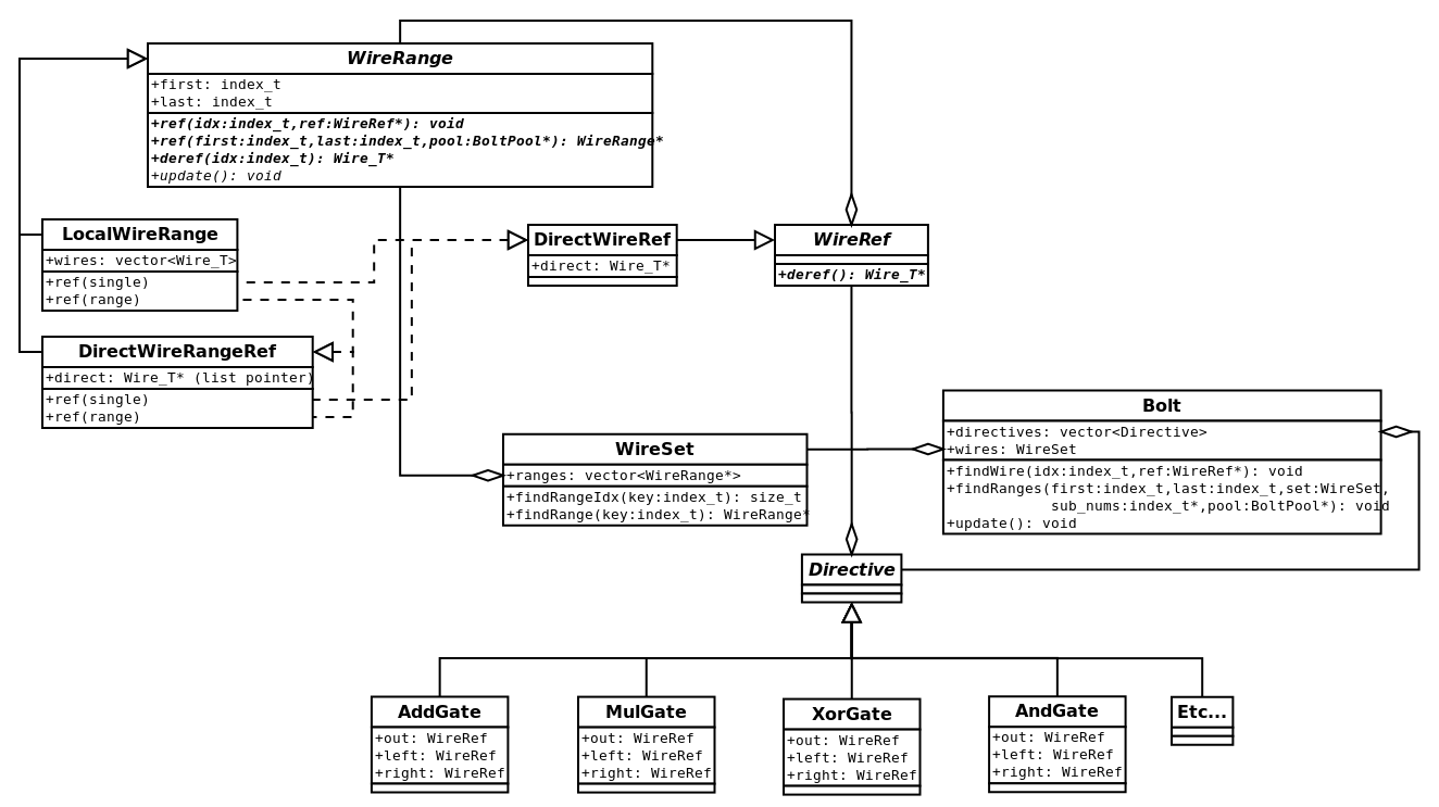
WireRange family, and along the bottom-right the Directive family. Connecting wires to directives the WireRef is above-center. The Bolt entry-point is pictured in the center-right, and its WireSet helper is below-center. Struct definitions can be found at wtk/bolt/wires.h and wtk/bolt/directives.hA Builder object (not shown) is responsible for translation of a single syntax-tree node (wtk::DirectiveList) into the BOLT structure.
If build succeeds, it guarantees that the relation, and consequently the produced BOLT structure, is well-formed and safe to evaluate.
The Builder optimizes the IR by analyzing one scope at a time.
In each scope, it follows these four steps:
-
Step 1: Reconstruct each scope’s memory layout.
-
Step 2: Preallocate space for wires.
-
Step 3: Rebuild each directive with pointers directly to preallocated space.
-
Step 4: Profit. (Well, okay. Execution of the scope will have a large constant-factor reduction in overhead)
Reconstruction is pretty simple.
We use a data structure which I’ve been calling a SkipList (although I’ve recently been informed that a SkipList is actually a multiply-linked-list with O(log(n)) access time, which this is not).
My SkipLists are more like "ordered range sets": an ordered list of ranges (first and last pairs) which define membership.
Thus upon entry to any scope of the IR, the first thing to be done is to traverse all directives, and insert every assigned wire into a SkipList, the "all list".
With all wires now accounted, they can be preallocated.
Local wires are to be allocated as LocalWireRanges in a WireSet.
The WireSet.ranges vector mirrors the structure of the local ranges within the all list.
Input and output wires are typically handled by the calling scope; we’ll cover them later.
Each directive is then rebuilt one by one. At each directive, the wires must be checked, to ensure that the relation is indeed well-formed. This is done with two additional SkipLists:
- assigned
-
for wires which were assigned by previous directives.
- deleted
-
to track
@deleted wires.
Input wires must be members of the assigned list and non-members of the deleted list.
Output-wires are then inserted (with failure on duplication) into the assigned list.
Once the directive is deemed acceptable, each wire may be looked up and referenced: Bolt.findWire(…) delegates to WireSet.findRange(…) and WireRange.ref(…).
Most of the time, this will produce a pointer directly to the wire, allowing the evaluation phase to skip out on safety-checks and lookup costs. Evaluation can still be considered safe, because the Build phase would have aborted before producing an unsafe pointer. The performance gain is especially effective with loops, because repetition allows a single directive to be reused many times.
Remapping Wires Between Scopes
In lieu of a conventional lexical scoping scheme, the IR uses a local scoping scheme with "remapping" from the calling scope to a local scope.
Variances in remapping lead to a family of WireRanges, responsible for handling various cases of remapping.
- Local
-
has ownership over a vector of wires in the local-scope. Lookup is performed via vector-indexing.
- Direct
-
is the simplest form of remapping, with a pointer into a containing scope’s local-scope. Lookup is performed via pointer-offset.
- Indirect
-
holds a pointer to another
WireRange, to which all functionality is delegated. - WireSet
-
Similar to Indirect, however it delegates to a
WireSetrather than aWireRange.
The Builder takes the responsibility for checking that any WireRange is safe to dereference before it is built.
In other words, the construction of an unsafe WireRange would be indicative of a poorly-formed relation.
Each WireRange has three essential functionalities which the Builder must guard.
-
producing a reference to a single wire (
ref(single)), -
producing a
WireRangereference to itself or a subset of itself (ref(range)), -
and dereferencing single wires within itself, as a requirement for Indirect referencing schemes.
Dashed arrows in the UML are used to indicate each WireRange's means of reference.
AnonFunction, Function, and Invocation. Additional WireRange forms are shown as needed for function gates.The goal for BOLT is to produce as many direct references as possible. In the following sub-sections, we’ll get into the remapping for each of the non-simple IR1 directives, starting from least to most complicated.
Anonymous Function
Anonymous functions are the easiest to remap, because they are used exactly once. First, the caller will check for usability of the input wires in the assigned and deleted SkipLists, and then for assignability of the output wires. When it knows the function is safe to call, it produces direct references for its local wires, and polymorphism — within its own remapped wire ranges — produces the simplest remapping it can for previously-remapped wires.
Named Function
Named functions are slightly more difficult than anonymous ones, because they may be reused multiple times.
To save time during the build phase, we want to reuse the Bolt structure built for the function.
To do this, remapping must be split between the function-body and each invocation.
In the function-body, a placeholder wire range is mapped into the the Bolt body.
A WireSetWireRangeRef is used, with a WireSet* pointer initialized to null.
The placeholder creates Indirect references to itself, so that the body can be built.
During evaluation, the WireSet* pointer is changed to non-null so that actual wires can be referenced.
At the invocation site, wires from the caller’s scope are mapped into a WireSet using the similar rules to an Anonymous Function.
At evaluation time, this WireSet is pointed to by the function’s placeholder.
Switch Statement
IR switch statements differ from conventional switches because all @cases must be processed to hide the switch condition wire.
After processing all @cases the output wires from the selected @case is multiplexed onto the @case's output wires.
This is complicated by @assert_zero directives, which are disabled in non-selected @cases and by @instance and @short_witness directives which must share input values across cases to avoid blowup in the stream size.
Building and evaluating a switch statement is sort of a three step process.
Remember that each @case has its own input list (as either a named or an anonymous function), but all @cases share the @switch's output list.
-
Each
@case's Instances and Witnesses counted and the maximum is taken as the@switch's output count.-
During evaluation, the
@switchconsumes inputs which are routed to@instanceand@short_witnessdirectives within the switch.
-
-
"Dummy" output wires and "legitimate" input wires are mapped into each
@case's body. -
During evaluation, after all
@cases are evaluated, the dummies are multiplexed into the legitimate outputs.
Step one happens dynamically during evaluation, aside from counting the maximum consumption of instance and witness wires.
The @switch will consume all the necessary inputs and places them in a special buffer (SwitchInputHandler).
The body of each @case is given a pointer to the buffer in place of the normal streams (wtk::InputStream).
@instance and @short_witness directives copy wires from the buffer rather than consuming from the stream.
Step two is again fairly straight forward.
As each @case has none of its own output wires (only the @switch's, at a top level), the total number of outputs can be counted, and a LocalWireRange may be allocated as "dummy" space for each @case.
Then the input wires can be mapped in, and processing of each @case continues the same as it would for a standard @call or @anon_call.
When processing the body during evaluation, a special case-enabled wire is carried to toggle inputs to @assert_zero directives.
The last step of build remaps each of the @switch's outputs to a special output WireSet.
At evaluation, the dummy wires are multiplexed, and each result is assigned to the corresponding wire in the output WireSet.
The BOLT system defaults to the Fermat’s Little Theorem trick described in section 6.3 of the IR spec.
However, ZK backends could improve upon this with dynamic generation of additional witness values.
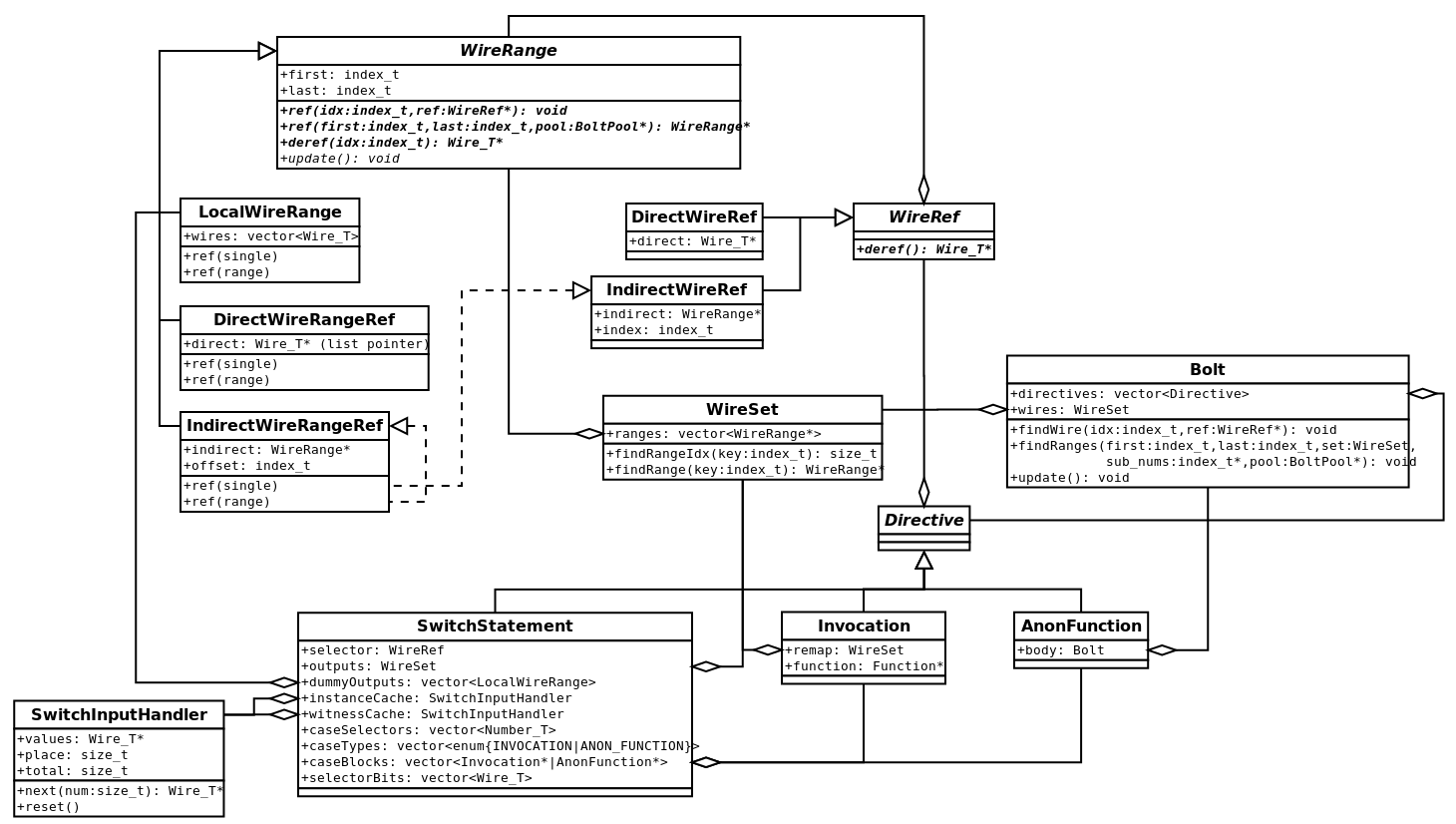
SwitchStatement type relies on Invocation and AnonFunction for each case, along with a SwitchInputHandler that manages reuse of instance and witness values.For Loops
For loops are where wire-remapping gets really tricky, because the remapping indexes change on each iteration, due to iterator-expressions and iterator-expression-ranges (from now on I will use "expression" synonymously with "iterator-expression" and "iterator-expression range", as a single "iterator-expression" is simply a range with a constant span of 1). BOLT has three code paths for processing a loop.
-
Shortcut, where the well-formedness of its iterations may be extrapolated from its bounds.
-
Soft Unrolling, where each iteration has its remapping tested individually, but all iterations share the same body.
-
Hard Unrolling, where each iteration has an individual remapping and body.
Shortcut and soft unrolling can be applied in a hybrid fashion where some expressions are shortcut and others are soft unrolled. Unfortunately, hard unrolling is an all-or-nothing deal.
IR specification compliance can be summarized to a few simple heuristics. However, the general case requires most of them be checked on each iteration.
-
Every input wire in every iteration must have been assigned previously.
-
Assignment could be before the loop,
-
Or in a prior iteration of the loop.
-
-
Every output wire in every iteration of the loop must be assignable.
-
The union of all iterations' outputs must be equal to the entire loop’s outputs.
-
Lastly, either the named function must receive the correct number of inputs and outputs, or the anonymous body must itself be well-formed on all iterations. Typically, the latter requires that all iterations have the same number of inputs and outputs.
-
There are some exceptions to having same-sized iterations, however these should be uncommon enough to be penalized by unrolling.
-
Detecting Shortcuts
BOLT does its best to come up with specific cases which it can shortcut, and attempts to fall back to unrolling as infrequently as possible. A trivial shortcut rule is if an input expression is constant and is assigned entirely before the loop. The non-trivial shortcuts will interpolate a total range (minimum through maximum values) for each expression, and show that the entire range is either referencable for inputs or assignable for outputs. To do this it has the following conditions.
|
Note
|
This isn’t to say that an extrapolation couldn’t be made with different conditions. These ones happen to be a fairly straight-forward baseline, and to cover many common cases of loops. |
- The expression must be a linear expression.
-
For a linear expression, the expression’s minimum and maximum values (forming the total range) will occur at a loop bound. This is also a prerequisite for later conditions.
-
A sub condition is that evaluation at bounds must not cause integer overflow. Integer overflow would cause a discontinuity, meaning the minima and maxima may occur on a middle iteration. Inductively, if a middle iteration causes overflow, then either the next or previous iteration would cause overflow until a bound is met.
-
- The expression must have the same span at the loops' bounds.
-
(including combinations of outer-loops' bounds, if the expression depends on outer-loop iterators) If all expressions meet this condition, then each iteration must have the same number of outputs and inputs.
-
As a sub-condition, the expression’s span must be 1 or more, to respect well-formedness rules.
-
- The output expression must have adjacent first and second iterations (or the loop may have only one iteration).
-
(e.g. i1.last == i2.first - 1 or i1.first == i2.last + 1) If this is the case, then the expression’s total range is uninterrupted and can be used to check that the loop’s outputs are covered.
-
As a condition of the loop, all output expressions must have disjoint total-ranges, but their union must be equal to the loop’s output.
-
- The output expression may depend only on the local loop iterator.
-
If the loop itself is repeated by an outer loop, then outputs may be remapped correctly in one iteration and incorrectly in another iteration. Non-dependence on surrounding loop-iterators eliminates that possibility.
- The input expression’s total range must be assigned before the loop.
-
When the expression’s total range is assigned prior to the loop, well-formedness can be checked in the assigned and deleted SkipLists.
-
Failing this, the input expression’s total range must intersect with some output expressions ranges. Both the input expression and the output expressions must be soft unrolled.
-
|
Note
|
An interesting side-effect of checking all these conditions is that they indicate that each iteration of the loop is independent of the others. That means that the loop could be parallelized or batch-amortized (however, as-built BOLT is definitely not thread-safe). |
Cutting Corners on "Sequential" Loops
The last condition of shortcut processing (that input expressions' total ranges must be preassigned) excludes a large class of "sequential" loops which could otherwise shortcut. In a "sequential" loop, an input expression follows closely behind an output wire, meaning that while it isn’t preassigned, it is assigned before use. These forms can be detected when an input expression’s total range overlaps an existing output expression’s total range. In this case, the following additional conditions allow us to continue shortcut processing rather than soft unrolling.
- The input expression must depend only on the local iterator.
-
This mirrors the condition of an output expression and assures consistent behavior across iterations of an outer loop.
- The difference between evaluations of output and input expressions at the loop bounds must be the same.
-
This ensures that both expressions have the same "total span", meaning that one won’t advance ahead of the other (because we already know that the expressions are linear and have constant span).
- The output and input expressions must "travel" in the same direction
-
If the expressions were to "travel" in opposite directions, then the input expression would be unassigned until the expressions "crossed their midpoint".
- There must exist a difference between the input and output expression’s total ranges which is assigned before the loop, and which covers the span of the first iteration of the input expression.
-
If this preassigned space did not exist, or if it did not cover the first iteration, then the first iteration of the loop would have a poorly formed input expression.
Building the Shortcut Loop
When these conditions are met BOLT builds a single loop body with special wire ranges to self-update on each iteration.
The loop’s body is a single Bolt object (rather than an Invocation or AnonFunction as SwitchStatement does), essentially inlining any named functions.
This mainly saves on code-complexity, at the occasional expense of memory usage, but it also avoids adding another layer of WireSetWireRangeRef.
Each expression is remapped as one of ShortcutLoopIndirectWireRangeRef, ShortcutLoopWireSetWireRangeRef, or, in the case of constant input expressions, remapped as-is.
ShortcutLoopXXWireRangeRefs have a constant range within the inner-scope of the loop, but reevaluate their expression on each iteration of the loop, redefining an offset into the outer-scope.
In most cases the inner-scope range can hold a single pointer to a contiguous outer-scope range ("Indirect").
However, it is possible for an expression to cross between ranges of the outer-scope (say from the input-wires into some local wires), thus a WireSet range must search the entire calling-scope.
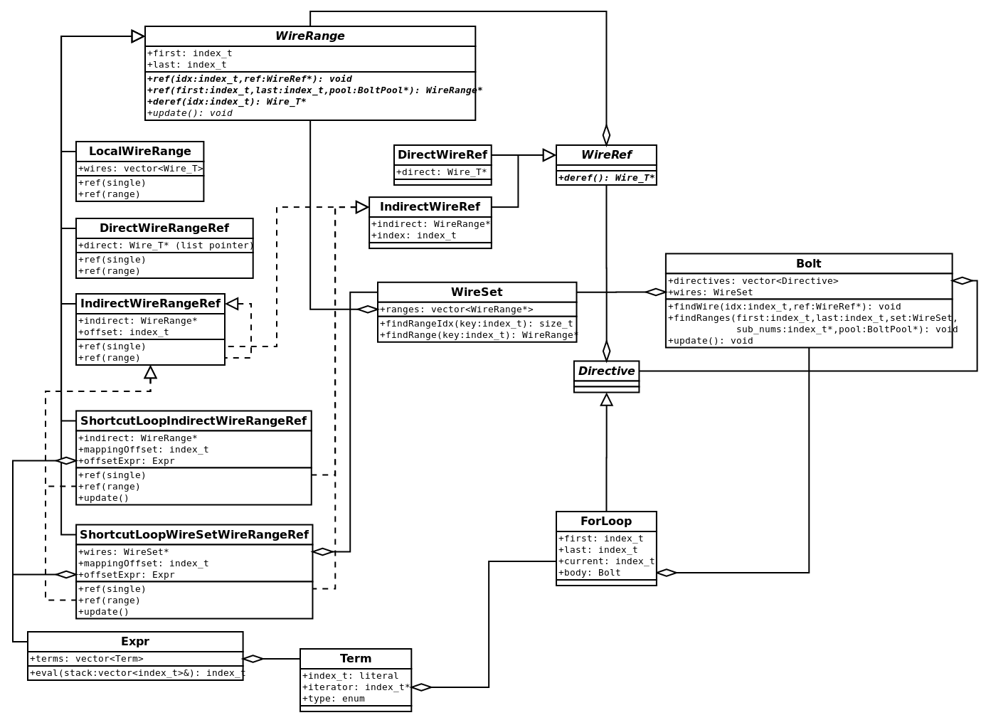
ShortcutLoopXXWireRangeRef types. The Expr type, a simple stack-calculator for updating expressions, is defined in the bottom left corner. The ForLoop directive is defined along the bottom.Soft Unrolling Path
Soft unrolling uses some of the same SkipLists from earlier to check the assignment of each wire-range on each loop iteration. If any of the expressions being unrolled depend on a non-local iterator, then soft unrolling must check the expression at each iteration of the non-local iterator to assure that the inner-loop is well-formed on every iteration of the outer-loop. Soft unrolling must also check for variable sized inputs or outputs, which would cause BOLT to fall back to hard unrolling.
When soft unrolling succeeds, a single SoftLoopWireRangeRef is mapped into the sub-scope.
It holds a vector of Translations which can be searched to map an inner-scope range to an offset in the outer-scope.
On each iteration of the loop a Mapping must update each Translation, as the span could change.
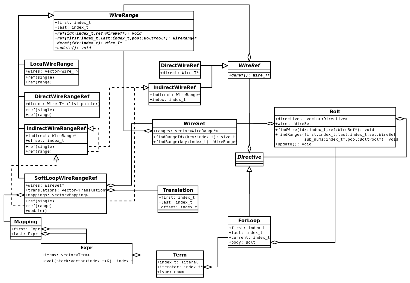
SoftLoopWireRangeRef family with Translation which when given an inner-scope index finds the outer-scope index and Mapping which updates the Translations on each call to update().Hard Unrolling Path
In the hard unrolling path, BOLT falls back to a single-pass interpretation scheme. One property this must maintain is that the build phase is expected to catch any relation well-formedness issues. For this reason the hard unroll path "pre-executes" the entire loop (repeating for any outer-loops) during the build phase, double-penalizing TA1 for emitting such an obnoxious loop (and myself for allowing such a loop in the IR at all ;-).
The main reason that hard unrolling would occur is due to a loop where the output list or input list has non-constant size.
BOLT cannot handle this because the WireRef cannot cache such a dynamic reference.
An example of hard unrolling is the "square loop" example. It is a pair of nested loops. The inner loop is fairly standard with 100 iterations and assigning its output range in 99, 98 … 0 order. The outer loop, however, assigns its 100 outputs in 10 iterations, where each iteration’s output size increases with the iterator’s square.
$0 ... $99 <- @for i @first 0 @last 9
  // Range is based on square(i), rather than simply i.
  $(i * i) ... $(((i + 1) * (i + 1)) - 1) <- @anon_call(@instance:0, @short_witness:1)
    $100 <- @short_witness;
    // This inner fills some locals and the output list
    $0 ... $99 <- @for j @first 0 @last 99
      $(99 - j) <- @anon_call($(100 - j), @instance:0, @short_witness:0)
        $0 <- @mul($1, $1);
      @end
    @end
  @end
@end
The Expr Stack Calculator
The Expr stack calculator updates offsets and mappings in BOLT Loops.
Although this article has used "expression" to refer to an "expression range" the Expr type implements only one bound of the range (e.g. two are needed to represent the entire range).
Initially the Expr.eval() method took nearly 50% of BOLT’s non-ZK runtime, however we were able to optimize this to about 15% to 20%.
Here are a few of its optimization tricks:
-
Passing the stack as a parameter eliminates allocation (faster than even stack-allocation, don’t ask me why, but C++ doesn’t like arrays on its stack). This optimization was done to the BOLT Prototype, nearly doubling its speed.
-
"Offset" and "multiple" operations push two parameters to the stack (
term.literaland*term.iterator, which were originally union members) before performing either an addition or multiplication. This saves two iterations of the calculator. -
A common case of the calculator is that it returns after just a single iteration (especially with offset and multiple operations). So we made these a fast-path which skips the stack entirely.
Results
We’re quite pleased with the results from BOLT.
The full-scale system does manage to improve upon the prototype: in the non-ZK setting it managed 4.3s compared to about 5.2s for the matrix 350 circuit, and I believe this was even with a larger prime.
But more important are the metrics with a ZK Backend.
We implemented BOLT’s callback API using the EMP QuickSilver backend.
When BOLT’s evaluate phase reaches each gate, it invokes a method from the from the wtk::bolt::Backend abstract class.
Child classes can override these methods to perform each gate using ZK.
For fair comparison with other approaches we developed the single-pass "PLASMASnooze" interpreter (a pun on FIREALARM) which shares backend integrations with BOLT. We also developed a streaming IR-Simple PLASMASnooze implementation. As IR-Simple’s syntax tree is a flat list, each gate can be processed immediately and then discarded, rather than storing it in a parse tree for later traversal. Lastly we also compare with the EMP C++ compiler which translates the IR to C++. We’ve plotted the end to end time (from IR to valid proof) for these approaches using the matrix circuit.
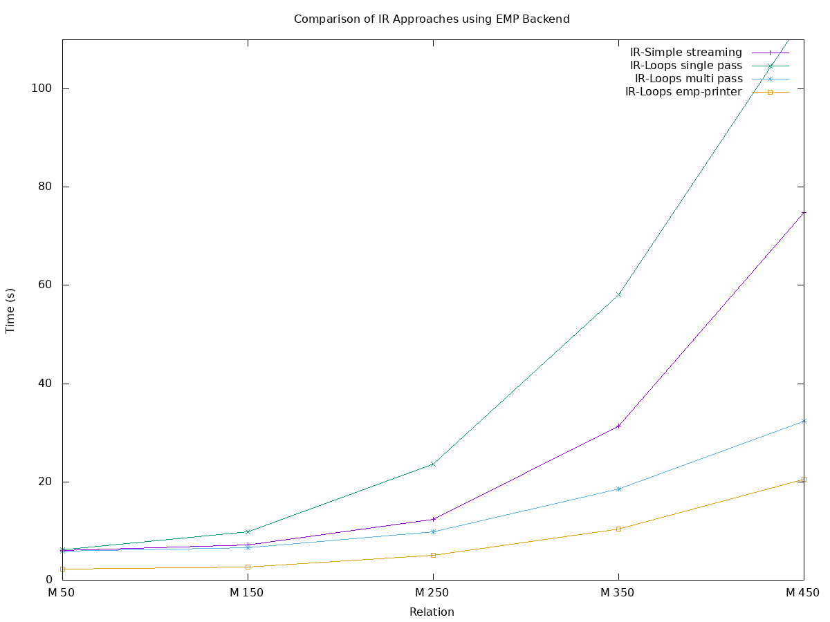
As expected, the IR-Loops single-pass (teal with crosses) is far slower than the IR-Simple in streaming mode (purple with plus signs). However the BOLT implementation (blue with stars) is 2x faster than streaming and the C++ implementation (orange with squares) is naturally even faster than that.
We also tested against the Finite State Machine circuit created by the T&E Team, which tests IR switch statements.
Unfortunately, we don’t have an IR-Simple version of this circuit, however we have a few interesting comparisons to make between the IR-Switch FSM circuit and its equivalent after switch statements were converted to multiplex circuits.
Additionally, the EMP backend can improve upon the Fermat multiplexer by creating and checking an additional witness value.
Unfortunately, we had issues compiling larger instances of the FSM circuit with EMP C++, due to gcc running out of RAM.
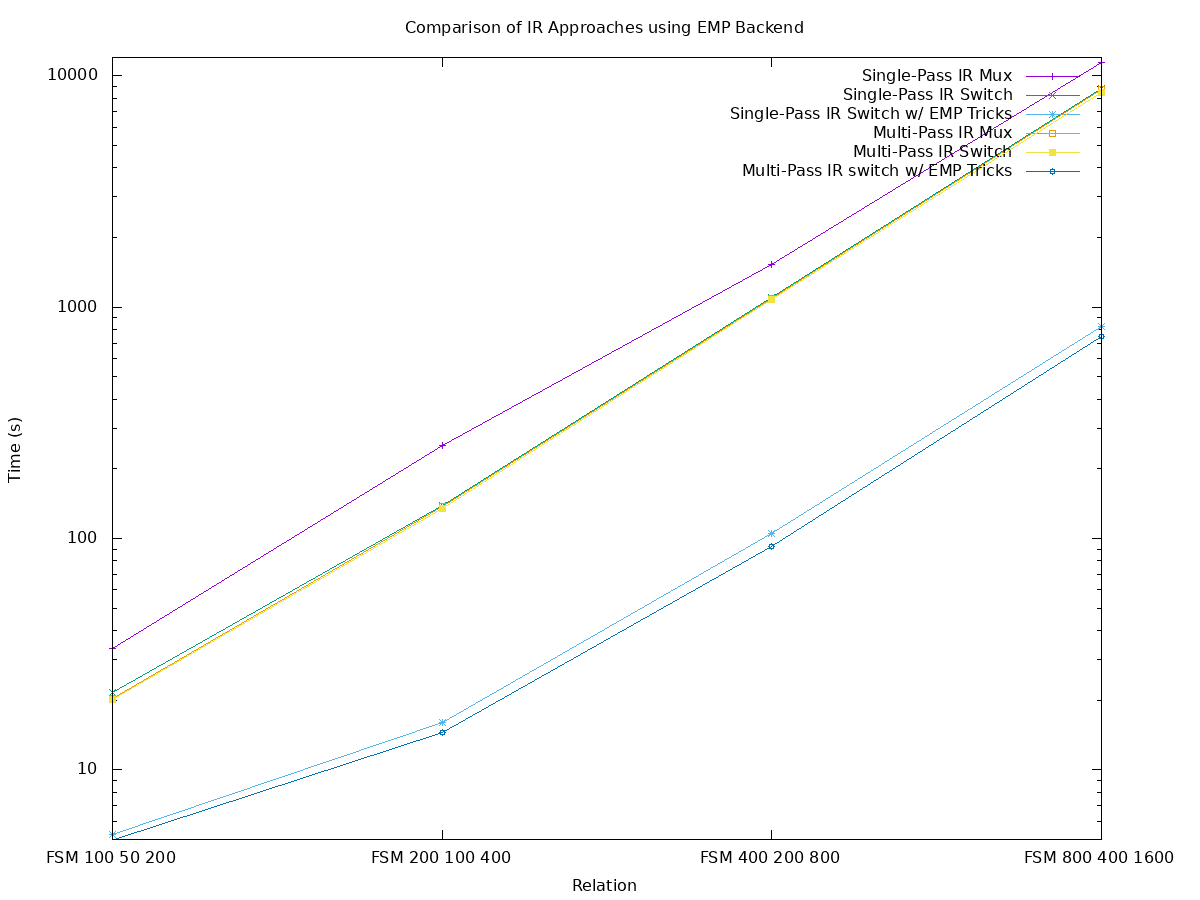
There are a few interesting takeaways from these test cases.
Most notably, single-pass switch, multi-pass multiplexer, and multi-pass switch are clustered fairly tight (yellow, orange, and green overlaps).
These all took between 8.4 and 8.8ks on the largest test-case.
This indicates that in the multi-pass interpreter the @switch directive is only a marginal improvement over a hard-coded multiplexer.
In the single-pass interpreter, however the @switch directive was extremely effective, going from over 11ks down to about 8.8ks.
The most dramatic gain, however, is from replacing the Fermat multiplexer with a witness-checking multiplexer ("EMP-Tricks"). These improve upon the Fermat multiplexer with an approximately 11x speedup. In this case, the largest test case runs in 826s for the single-pass (aqua with stars) and multi-pass (blue with circles) further improves that by about 10% to 748s.
Conclusion
We designed and developed the BOLT system after noticing that our compact IR-Loop circuits were much slower than their flat/non-uniform equivalents. We wanted to understand and avoid this slowdown. The BOLT system accomplished this goal, helping us understand how time was being spent between ZK gates. In the process, we managed to improve significantly upon flat circuits. Overall, we hope that following along with our BOLT development has given the reader an appreciation for the overhead spent between ZK gates and some insight into optimizing both ZK circuits and backends.
If you’re interested in using BOLT to speed up your own ZK backend when using the SIEVE IR, have a look at the WizToolKit tutorial for integrating backends.